October 25, 2021
NSX-T Federated VCF Regions (VCF Multi-Region)
A Step-by-step approach
A Written Guide to NSX-T Federated VCF Regions
Repeat the same on the third and final GM node.
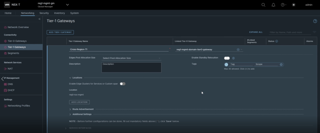
Navigate to Networking -> Tier-1 Gateways > Add Tier-1 Gateway.
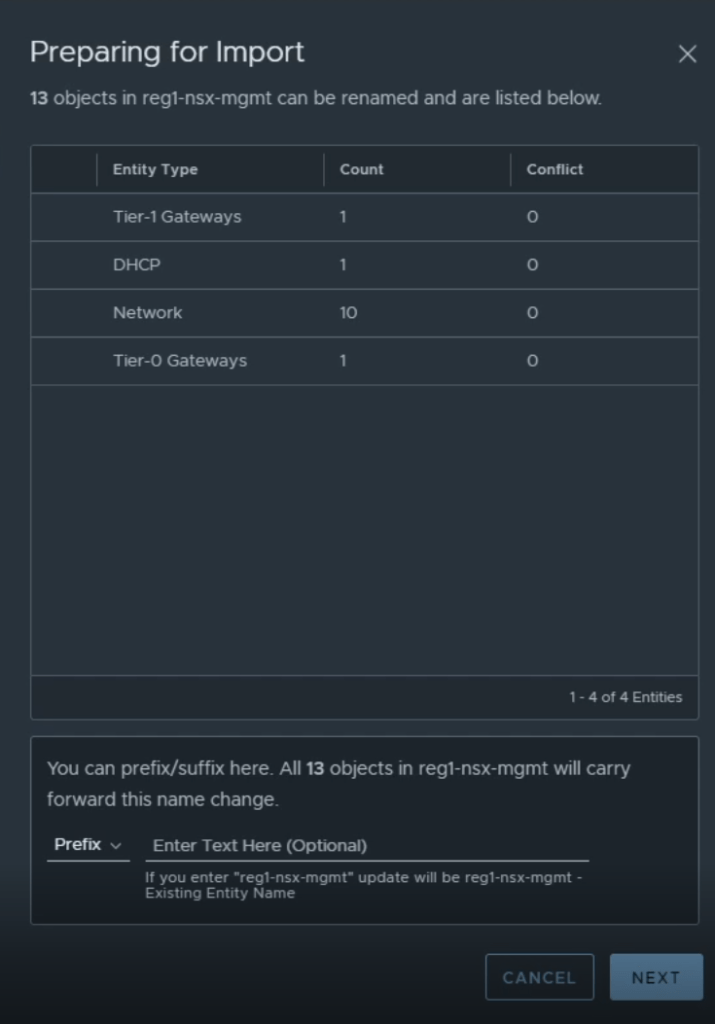
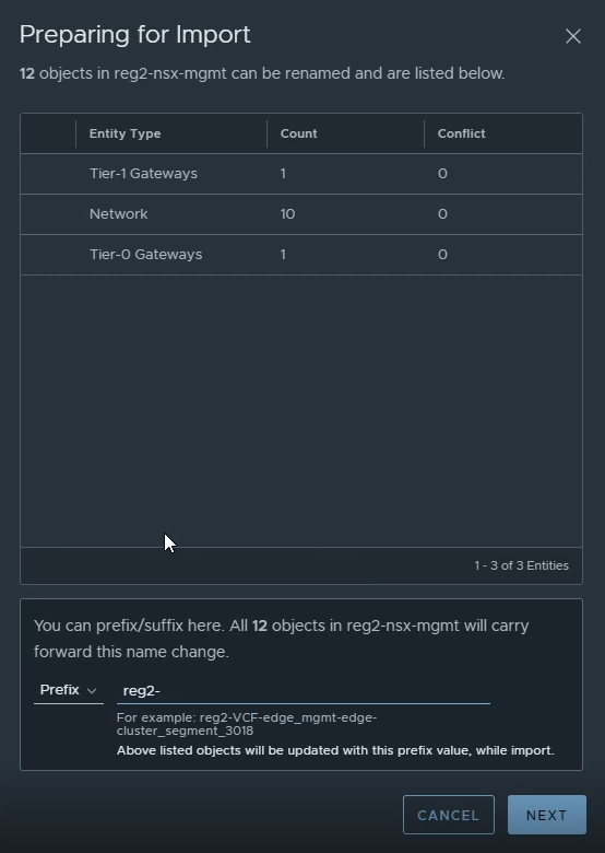
If you added a prefix to location 1’s objects, make sure you do not use the same one during this import. Confirm on the next screen and click on import.
As mentioned in this article and linked video, both show the process to federate the Management Domain. The same process must be repeated for any subsequent Workload Domains, including the deployment of additional Global Manager appliances. The region-specific Workspace One appliance can be re-used for all NSX-T components in the region.
Step 1: Deploy NSX-T Global Managers (GM)
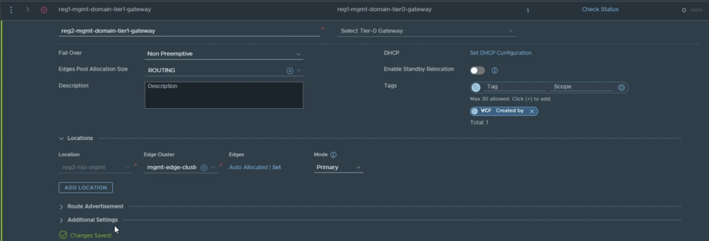
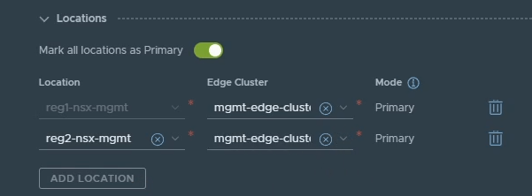
In the Locations section, click Add Location, the second location should show up on the second line, ensure you select the Edge cluster for the location as well. Refer to the image below. Click save once complete.
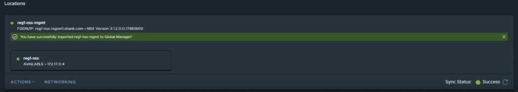
If you navigate to the networking tab and click through the gateways or segments, you will be able to see the objects that were imported.
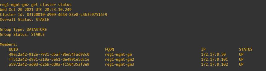
- reg1-mgmt-gm
- reg1-mgmt-gm2
- reg1-mgmt-gm3
Get The API Thumbprint
Refer to Step 4, for instructions on obtaining the api thumbprint.

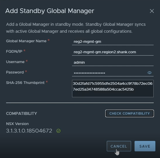
In the Global Manager UI, navigate to System -> Location Manager – > Add Standby. Refer to Step 4 for instructions on obtaining the thumbprint.

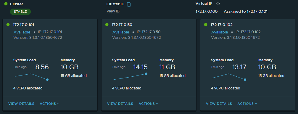
Verify the cluster status and set the cluster VIP
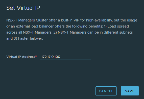
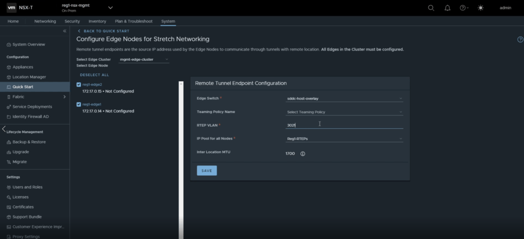
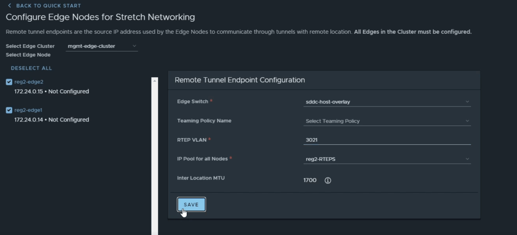
Note: this subnet must be routable with the RTEP VLAN in the first location, if there are firewalls between locations, ensure TCP 443,1236 and UDP 6081 are open bi-directionally.
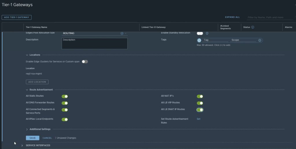
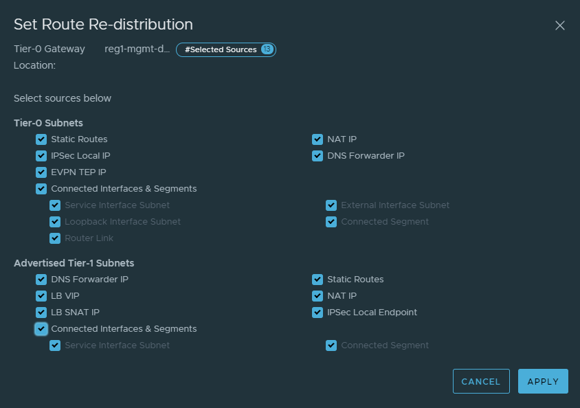
You will need to update the Route Advertisement options for the gateway, as this is a VCF environment, it is best to enable all options. Click save once complete.
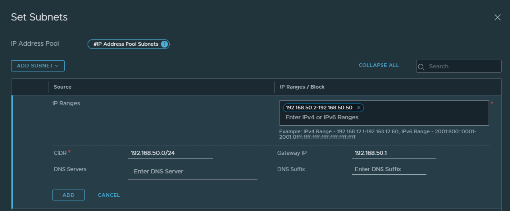
Navigate to Networking -> IP Address Pools -> Add IP Address Pool. Give it a name, click on subnets and enter the RTEP VLAN subnet details for this location. You can choose between IP Block or IP Ranges, in this example I am using a range. Refer to the image below, the fields not populated are not required.
Whilst in edit mode of the gateway, scroll down to Route Re-Distribution and click on Set for the second location that was added.
Step 2: Integrate Region 1’s Global Manager with vCenter and Workspace One Access
Once the appliance is booted for the first time, it takes you through an initial setup. This setup includes specifying passwords and whether you wish to use the internal database or not. Upon completion, it restarts the services and waits for the appliance to become available.
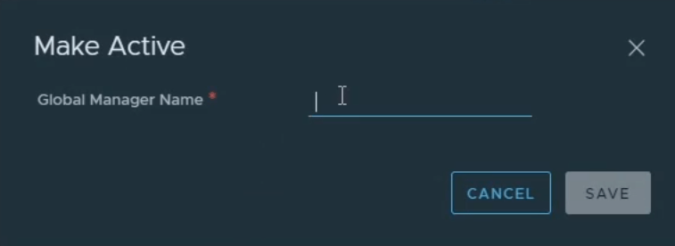
You will be presented with the below screen, enter a name for the primary cluster, I tend to follow the DNS entry of the VIP. It doesn’t have to be an FQDN.
Once this is complete, all location 2’s objects should be imported.
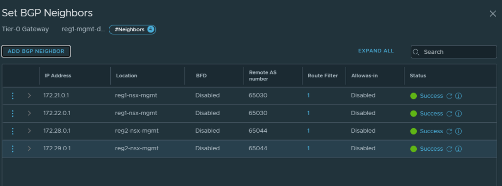
If all configuration is correct, all peers should be successful.
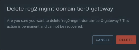
Navigate to Networking -> Tier-0 Gateway -> Delete Location 2’s Tier-0 gateway.
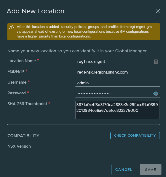
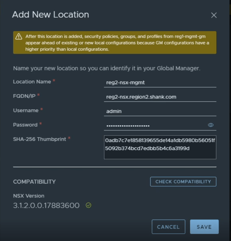
Navigate to System -> Location Manager -> Add On-prem Location. Populate the details relevant to your second location, as can be seen in the image below. Click save once complete.
Use an OVA to manually deploy Workspace One Access to the management domain cluster. Ensure it is up and running before proceeding. The OVA can be found here.
reg1-mgmt-gm> get cluster config

Sun Oct 17 2021 UTC 07:02:16.491

Cluster Id: 83120010-d909-4644-83e8-c463597516f9

Cluster Configuration Version: 0

Number of nodes in the cluster: 1
Node UUID: 49ec2a42-912e-7931-dbaf-8be54fad93c0
Node Status: JOINED
ENTITY UUID IP ADDRESS PORT FQDN
HTTPS d6d973dc-6661-43f5-8845-78cf8c537264 172.17.0.50 443 reg1-mgmt-gm
ASYNC_REPLICATOR f84a75b4-1a53-4635-ba4e-3103597d59ea 172.17.0.50 - reg1-mgmt-gm
CLUSTER_BOOT_MANAGER d59d44b8-acc1-4574-bf38-a1d37719c67b 172.17.0.50 - reg1-mgmt-gm
DATASTORE 8636a99c-6455-4cb1-a923-26ca1e0824d2 172.17.0.50 9000 reg1-mgmt-gm
GLOBAL_MANAGER daffb0c5-5106-477a-973e-2fab4bcbb4ab 172.17.0.50 - reg1-mgmt-gm
MONITORING d5182df7-b4a8-4062-951b-b7be1b35821c 172.17.0.50 - reg1-mgmt-gm
MANAGER c94ac304-6f4c-4468-95ba-b47c12a86a00 172.17.0.50 - reg1-mgmt-gm
Join GM2 and GM3 and form a cluster
RTEPs are a crucial component to Federation. RTEPs are an additional TEP interface instantiated on Edge nodes and similar prerequisites apply to them as with the other TEP interfaces.
To add the first location, on the same screen as above, scroll down and click on add on prem location.
To achieve this, you will have to log into the VIP of the Global Manager cluster in Region 2 and perform the integration steps. While the Active and Standby Global Manager clusters sync some data, Workspace One integration and compute managers are not something that is synced across the clusters.
Integrate the Global Manager cluster with Workspace One Access
Step 3: Make Region 1’s Global Manager (Cluster VIP) Active
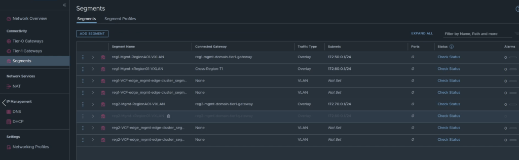
In this example I delete the second cross-region segment imported from Region 2, however, if you prefer you can disconnect it and not use it.

With Federation, there are new management plane constructs, they are Global Managers and Local Managers. Global Managers are appliances that have been deployed using the Global Manager role during OVA deployment. The Global Managers are responsible for synchronizing objects between Global Manager clusters and Local Manager clusters for both local and remote sites.
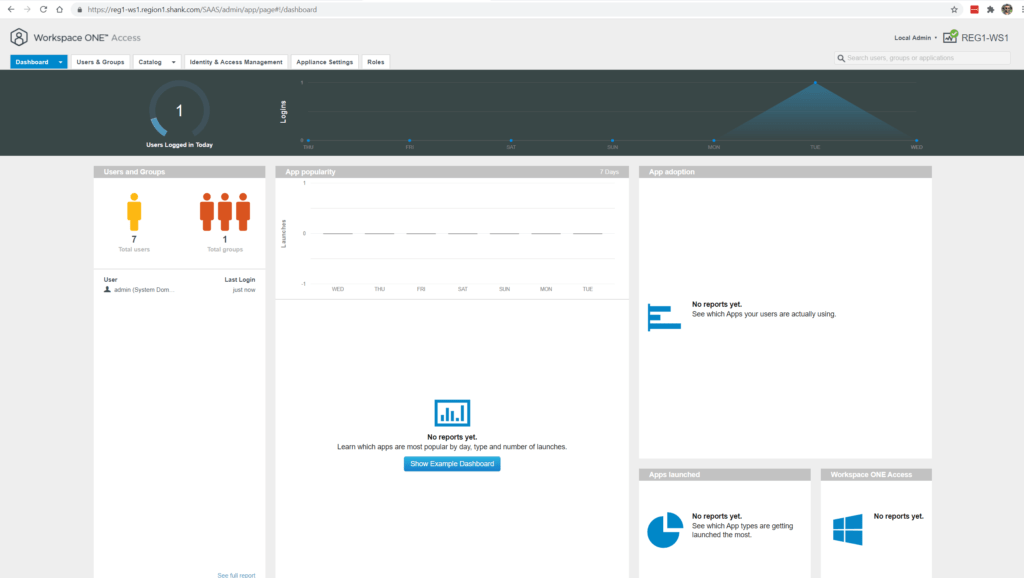
At this point you should be able to browse to https://<fqdnofWS1/admin>. Login with admin and you should be presented with this screen.
Step 4: Add the first on-prem Location
Populate the details as shown in the image below, changing it to suit your environment.

Navigate back to Global Manager > System > Location Manager, continue configuring the RTEP interfaces.
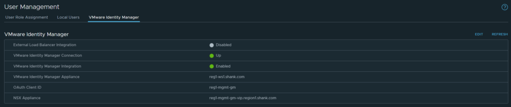
This means identity management configuration was successful and you are able to assign roles and permissions as required for your deployment.
Step 5: Import Local Manager Objects and configure networking (RTEPs) (detailed)
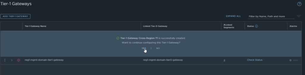
You will be prompted if you want to continue configuring the gateway, click on yes.
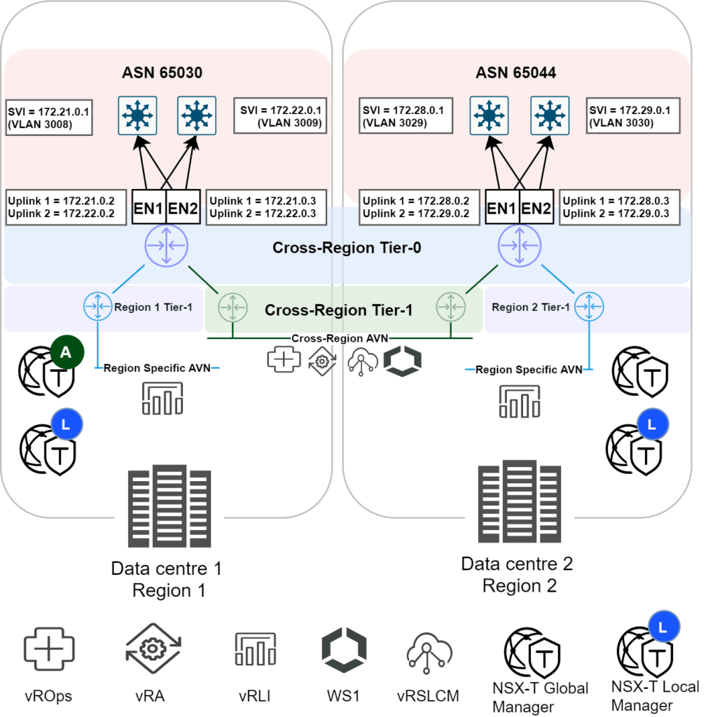
This step is where the gateways are stretched across locations. Before demonstrating the process to accomplish this, it makes sense to provide a diagram of the end-state after all interfaces, gateways and segments have been completely configured. This will hopefully provide you with a clearer networking picture to assist with deployment in your own environment.
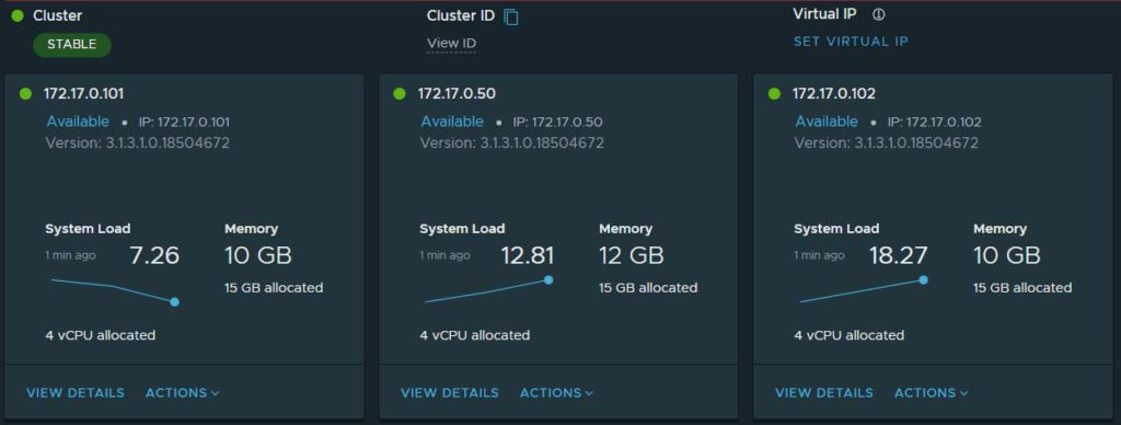
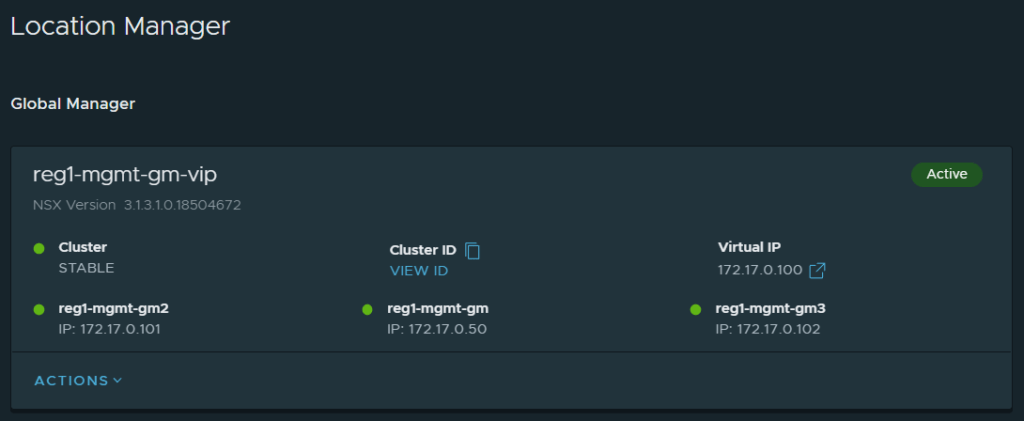
Once complete, the VIP will be assigned to one of the cluster nodes, as seen in the image below.
You will no longer be able to edit this object on the Local Manager, the option is greyed out. It must be edited from the Global Manager interface.
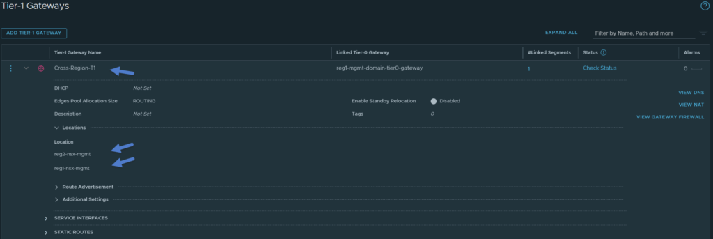
Navigate to Networking -> Tier-1 Gateways -> Edit both site specific Tier-1 gateways. Ensure that each site specific Tier-1 gateway is only assigned the location they are in. Refer to the image below.
The diagram earlier in this step showed two SVI’s for the second region, 172.28.0.1 and 172.29.0.1, these are the BGP peers that must be configured.
Importing Objects
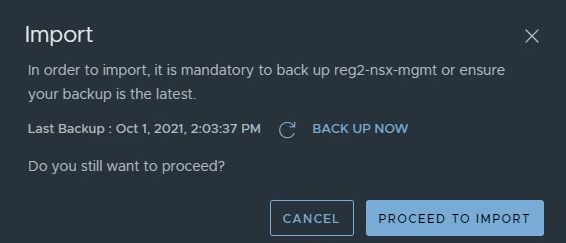
Ensure a backup is taken, otherwise you will not be able to proceed.
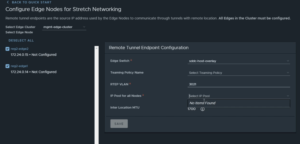
In this case, no IP Pools were displayed in the menu (refer to the image below). This was on purpose, to demonstrate how to create these IP Pools.
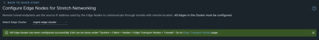
You will be prompted with a green banner when the RTEPs are configured successfully.
Preqreuisites.
On the first GM that was deployed, run the command below. This will retrieve the API thumbprint on the manager which will be used to join the subsequent managers and form a cluster.
Repeating the same process that was completed for Location 1, navigate System -> Location Manager -> Find the new location and click import on the blue banner.
Similar to the first location, it is now time to add the second location. Once we add the second location in, we are then able to stretch the segments and gateways across.
To configure RTEPs, navigate to System -> Local Manager -> Networking (under the newly added location).
Configuring RTEPs (Region 1)
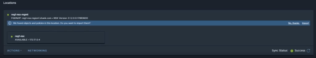
Once the first location is on-boarded, you are prompted to import the configuration from the Local Managers. It is important to note that you will only be prompted once, if you dismiss this notification or complete the process, you cannot do this again. You will also not be able to import configuration until you have a valid and successful backup.
Now that the GM cluster is configured, the management domain’s compute manager (vCenter) can be added to the Global Manager cluster and it can be integrated with Workspace One Access for Identity Management.
- Each site must have a VLAN configured for RTEPs, they do not need to be stretched
- Each RTEP subnet between sites must be routable
- It is recommended to have an MTU of 1700
- Port 6081 must be open between the subnets
Click save and close editing once complete.
root@reg1-mgmt-gm2> openssl s_client -connect ws1a.fqdn:443 < /dev/null 2> /dev/null | openssl x509 -sha256 -fingerprint -noout -in /dev/stdin

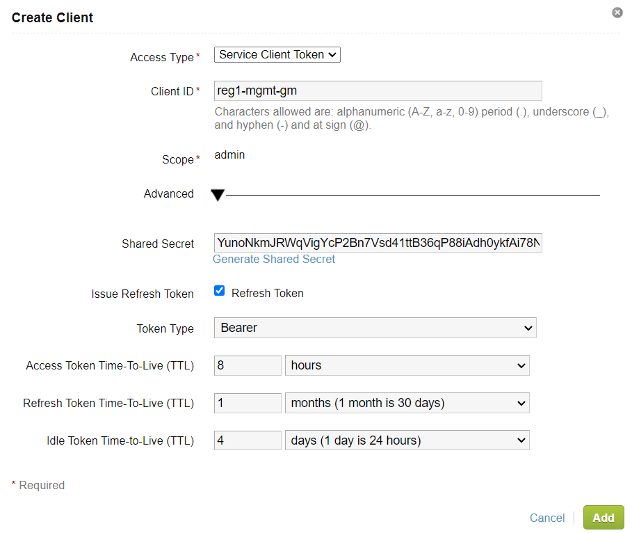
Fill in the details accordingly, pay close attention to the following fields.
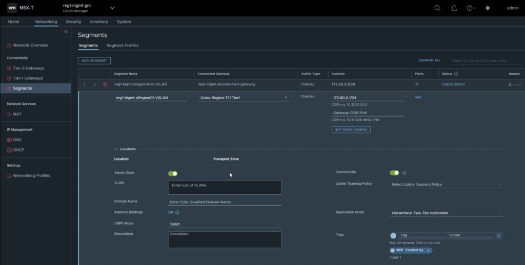
Navigate to Networking -> Segments -> Edit the xRegion Segment, save once complete.
Step 6: Create the Global Tier-1 Gateway
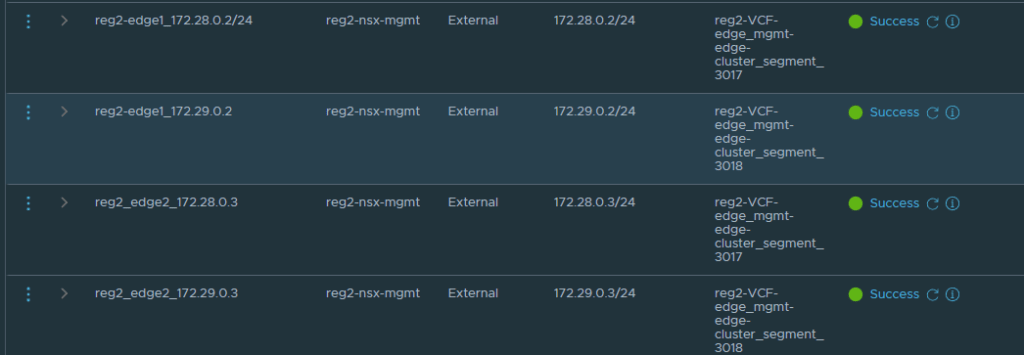
All interfaces should have been created successfully.
This step involves creating a new Tier-1 gateway that will be called Cross-Region-T1, this is the gateway that will have the Cross-Region AVN attached to it. Keep in mind, at this point only one location exists, therefore, the gateway is technically not yet stretched.
Navigate to System -> Location Manager -> Click Networking under location 2. Follow the same process as you did for location 1.
NOTE: Since this post was written, the official steps no longer require you to add the vCenter servers as compute managers. Please ignore the references that request you to do so. Doing so does not invalidate your deployment if you have already done it, it just adds no benefit. You will be able to add the management domain compute manager, however, will not be able to achieve the same result with the workload domain. When you attempt to deploy the appliances for the workload domain, they will be deployed onto the workload domain nodes, which is not what you should be doing, all management appliances should be deployed into the management domain.
It’s time for some clean up, navigate to Networking -> Segments.
Step 7: Re-plumb the Cross-Region Segment
It should look like this once complete.
This step is simply changing the Tier-1 gateway that the xRegion (Cross-Region) AVN is plumbed into. Refer to the image below.
Step 8: Add the second on-prem location and import objects
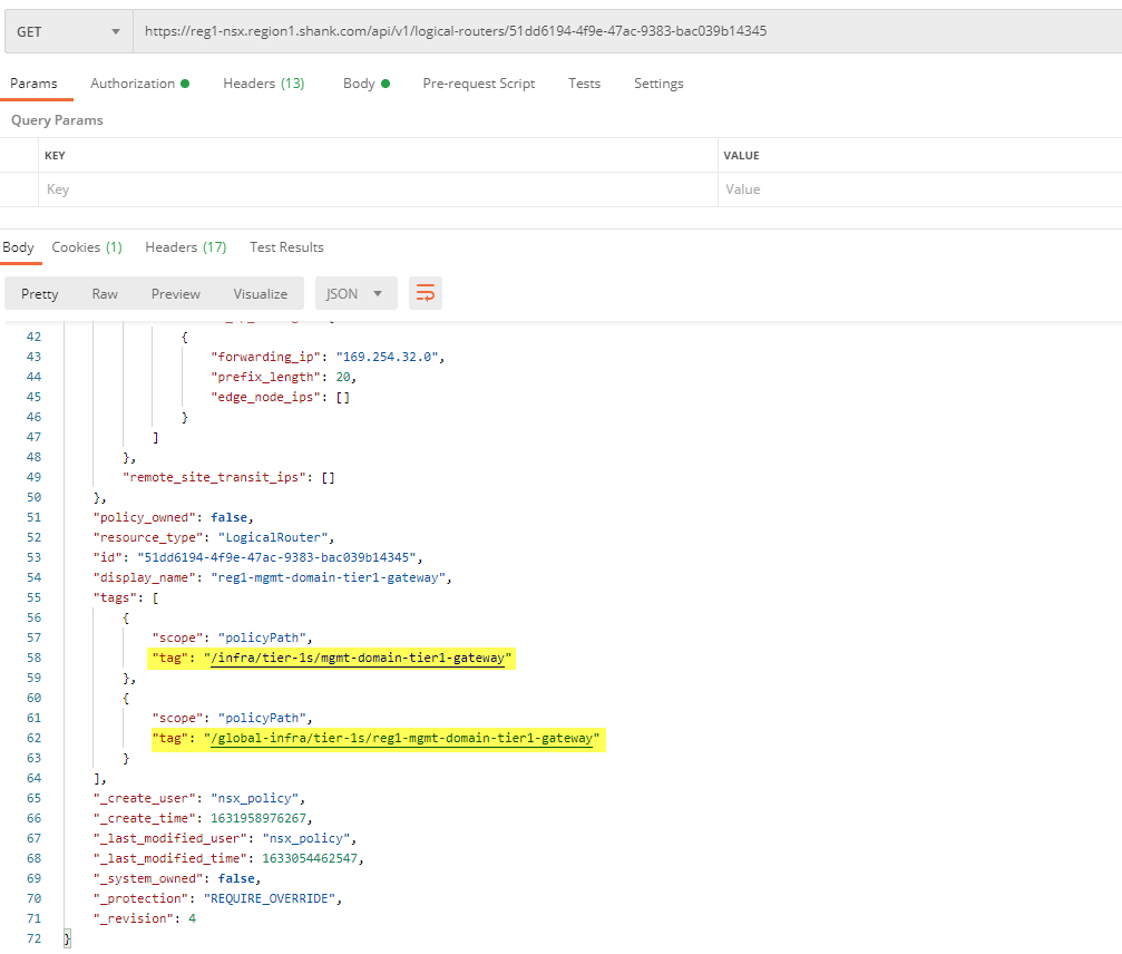
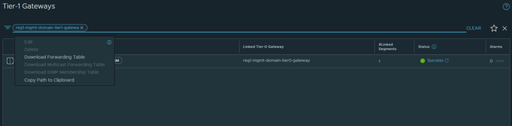
As you can see from the image below, the policy path for reg1-mgmt-domain-tier1-gateway gateway now includes /global-infra/tier-1s/reg1-mgmt-domain-tier1-gateway and the local policy path. Even though you are able to list the logical routers using the path shown, you are not able to configure it here.
Related
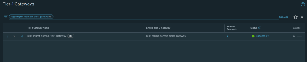
When viewing objects from a Local Manager, all imported objects and objects created globally are marked with a GM, as can be seen in the image below.
Step 9: Modify the second locations’ imported objects
Enter a name for the gateway and the Tier-0 gateway it is to be linked to, refer to the image below. Click save one complete.

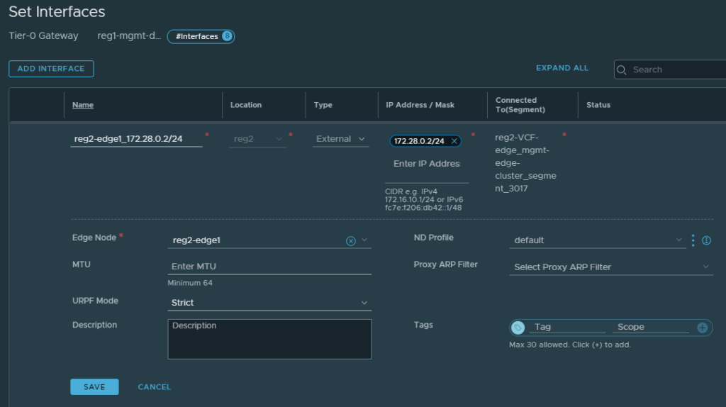
The rest of the fields can remain as their default settings. The image below is an example of one of the Edge interfaces in Region 2, repeat the process for each interface that needs to be created, click save after completing each interface.
This article will cover the Federation process demonstrated in the video, however, the real purpose is to dive deeper into the network and NSX-T Federation logical constructs. The table of contents below lists all the steps that will be discussed, with hyperlinks to make it easier to jump to the various sections.
reg1-nsx> get certificate cluster thumbprint
Navigate to BGP -> BGP Neighbors -> Set -> Add BGP Neighbor.
Before demonstrating the process of importing objects, i’ll quickly touch on what this is actually achieving.
Delete Location 2’s Tier-0 Gateway
The output below was is from the first GM deployed in the cluster, however, it may be run on any of them. It is important to note that the GM nodes must satisfy the minimum RTT of 10ms within the same cluster and have complete IP connectivity with one another. In order to be able to set a VIP, all nodes must be deployed onto the same subnet.
Configure RTEPs
After clicking import, a dialogue box pops up showing you the count and types of objects that will be imported. At the bottom of this screen you are able to add a prefix/suffix to the names of the objects that will be imported. For example, adding reg1- will import a Tier-0 gateway named Tier-0, as reg1-Tier-0. This prefix/suffix will apply to all objects being imported.
To begin, manually deploy all three Global Manager nodes using an OVA. The three managers that have been deployed in this example are called.
reg1-mgmt-gm2> join 172.17.0.50 cluster-id 83120010-d909-4644-83e8-c463597516f9 username admin password VMware123!VMware123! thumbprint c36f9ee858c3fa6e2a0ff78aa32477feb4c0fbd081ebceba2654123d10cabe49
This step will not be repeated for this example, however, refer to Step 2 for instructions on integrating with the region specific Workspace One and adding the compute manager. Ensure you are integrating the Region 2 Global Manager cluster with the Region 2 Workspace One appliance and vCenter!
In this article you have been shown how to configure NSX-T Federated VCF Regions, from an NSX-T perspective. Hopefully you found this article useful, please feel free to leave a comment.
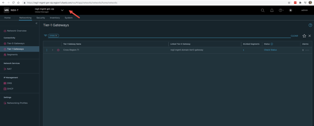
For reference, the image below shows the Cross-Region-T1 configured with both locations.
Step 11: Stretch and configure the Tier-0 Gateway (detailed)
Set the cluster VIP by selecting SET VIRTUAL IP and click Save. Ensure the VIP has a forward and reverse DNS record for the region.
Configure the second location on the stretched Tier-0 gateway
Note: Local Managers are the NSX-T Manager appliances that are not in Global Manager mode and have data plane nodes enabled and configured on them.
You will need to obtain the thumbprint of the Workspace One Access appliance, in this example I have SSH’d onto a Global Manager, logged in as root and issued the command below, which will display the SHA256 thumbprint.
Configure Interfaces on the second location Edge nodes
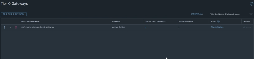
Navigate to Networking -> Tier-0 Gateways -> Edit the Tier-0 gateway.
Global Managers do not deal with the data plane, this is left to the Local Managers and Transport Nodes. Global Managers ensure objects configured as a global object are synchronized with the standby Global Manager cluster and Local Manager clusters. It does so using the async replicator service on port 1236 which is run by the application proxy service. The latter service is responsible for connectivity between Global Manager clusters (active / standby) and Global Manager and Local Manager clusters.
- Name – Give it a name easily identifiable
- Location – Select which location to create the interface (in this case either Region 1 or Region 2)
- Type – External
- IP Address / Mask – Interface IP Address
- Connected To – Which segment to use for this interface
- Edge Node – Which Edge node the interface will be instantiated on
Once connectivity is established and all Edge nodes (both sites) are deployed, a GENEVE tunnel (UDP 6081) is formed between remote Edges. It is important to note that these tunnels are only formed cross-site and not between RTEP interfaces on the same site. Once the tunnel is up, iBGP peering sessions are formed between the Edges for route advertisement and data transport.
If you missed it earlier, click on this link The intention of this post is to provide some of the finer details that were discussed in my latest video, titled “Deploy NSX-T Federated VCF Regions (VCF Multi-Region)“ to view the video.
Configure Route Redistribution
When adding an interface for a specific Region, pay close attention to the following fields.
This step is ensuring there are region specific Tier-1 gateways that are not stretched across locations. These will be used for the site specific AVNs which will have vRealize Log Insight connected to them.
Configure BGP neighbours in the second location
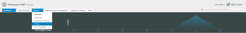
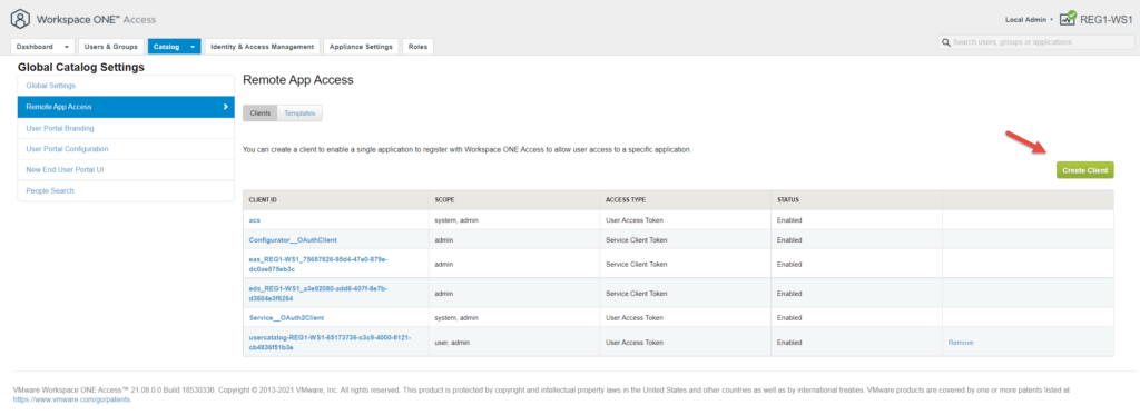
Click on Catalog -> Settings -> Remote App Access -> Clients -> Create Client
Fill in the details as required by your environment.
First click on the drop-down menu in the black banner, and select the second location.
- IP Address – Neighbor IP address
- Location – Location of the peer
- Remote AS Number – ASN of the upstream peer
- Source Address – peering to occur from the specified addresses
- Password – If you have configured the peer with a password
Importing objects from a Local Manager is essentially promoting objects that are configured on a Local Manager cluster, into global objects. Once this process is complete, those objects become read-only on the local managers and are generally only configurable on the Global Manager appliance.
Step 12: Clean-up objects
Examples of other attributes that are synced between sites includes; Groups and their memberships, segment tables (MAC / ARP etc).
This step will include instructions for importing objects and configuring RTEPs to enable cross-site communication.
Step 13: Ensure Region Specific Tier-1s are configured correctly
Click on Add Route Re-distribution, give it a name, and click on set. Check all the settings relevant to your environment, in this example all are checked. Refer to the image below. Click Apply once done, click Add on the previous screen and save the configuration.
reg1-mgmt-gm> get certificate api thumbprint

c36f9ee858c3fa6e2a0ff78aa32477feb4c0fbd081ebceba2654123d10cabe49
The thumbprint can be retrieved by SSH’ing onto any of the the Local Managers deployed (NSX-T Manager not in global mode for the region) and issuing the command shown in the snippet below.
Step 14: Add the standby manager
Navigate to Networking -> Tier-0 Gateways -> Edit the Tier-0 gateway -> Click Set under Interfaces -> Click Add Interface.
Step 15: Add Compute Manager and Workspace One Integration for Region 2
The intention of this post is to provide some of the finer details that were discussed in my video.
The cluster status can also be checked in the web UI, in this case I browsed to the web interface of the first node https://reg1-mgmt-gm.region1.shank.com -> System -> Global Manager Appliances. This is also where we will be setting the VIP for the cluster.
Conclusion
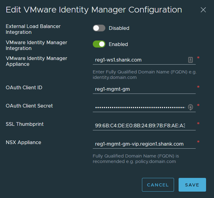
Browse to the VIP of the Global Manager cluster, navigate to System -> User Management -> VMware Identity Manager -> Edit.
The first thing you will need to do once the objects from location 2 are imported is, remove the Tier-0 gateway attachment from location 2’s Tier-1 gateway. The reason you need to do this is, the Tier-0 gateway that was imported from location 2 will be deleted. The end result here is to have a single stretched Tier-0 gateway, so there is no use for the second Tier-0 gateway. Refer to the image below.
Populate the details, changing the required fields to match your environment.